2015년 5월 7일 목요일

아두이노 나노

 던전워즈
원문: http://www.arduino.cc/en/Main/ArduinoBoardNano


Overview(개요)

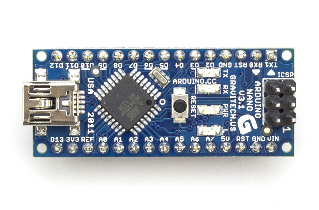
The Arduino Nano is a small, complete, and breadboard-friendly board based on the ATmega328 (Arduino Nano 3.x) orATmega168 (Arduino Nano 2.x). It has more or less the same functionality of the Arduino Duemilanove, but in a different package. It lacks only a DC power jack, and works with a Mini-B USB cable instead of a standard one. The Nano was designed and is being produced by Gravitech.
아두이노 나노는 작고 완전한, ATmega328(아두이노 나노 3.x) 또는 ATmega168(아두이노 나노 2.x)에 기반한 브레드보드 친화적인 보드이다. 이것은 아두이노 Duemilanove의 같은 기능과 비교했을때 거의 유사하다. 하지만 이들은 다른패키지다. 나노는 DC 파워 젝을 가지고 있지 않지만, 대신에 표준 Mini-B usb 케이블로 작업 할 수 있다. 나노는 Gravitech에 의해 디자인되고 생산되었다.

Schematic and Design(도식과 디자인)

Arduino Nano 3.0 (ATmega328): schematicEagle files.
Arduino Nano 2.3 (ATmega168): manual (pdf), Eagle filesNote: since the free version of Eagle does not handle more than 2 layers, and this version of the Nano is 4 layers, it is published here unrouted, so users can open and use it in the free version of Eagle.

Specifications(상세):

MicrocontrollerAtmel ATmega168 or ATmega328
Operating Voltage (logic level)5 V
Input Voltage (recommended)7-12 V
Input Voltage (limits)6-20 V
Digital I/O Pins14 (of which 6 provide PWM output)
Analog Input Pins8
DC Current per I/O Pin40 mA
Flash Memory16 KB (ATmega168) or 32 KB (ATmega328) of which 2 KB used by bootloader
SRAM1 KB (ATmega168) or 2 KB (ATmega328)
EEPROM512 bytes (ATmega168) or 1 KB (ATmega328)
Clock Speed16 MHz
Dimensions0.73" x 1.70"
Length45 mm
Width18 mm
Weigth5 g
운용 전압은 5v, 입력전압은 7 ~ 12v가 권장되며, 6 ~ 20v까지가 한계이다.
14개의 디지털 입출력 핀을 가지며, 이중 6개는 pwm출력이 가능하다.
8개의 아날로그 입력핀을 가지고 있다.
입출력핀의 전류는 핀당 40mA이며, 16KB(ATmega168) 또는 32KB(ATmega328)의 플래시 메모리를 가지는데 이중 2KB를 부트로더가 사용한다.
1KB(ATmega168)또는 2KB(ATmega328)의 스태틱 메모리를 가지고 있으며, 512바이트 또는 1KB의 EEPROM을 가지고 있다.
클럭스피드는 16MHz이며, 0.73인치 * 1.70인치크기다.

Power(전원):

The Arduino Nano can be powered via the Mini-B USB connection, 6-20V unregulated external power supply (pin 30), or 5V regulated external power supply (pin 27). The power source is automatically selected to the highest voltage source.
아두이노 나노는 Mini-B usb연결을 통해서 전원을 공급하거나, 6 ~ 20v의 정제되지 않은 외부전원(30번핀) 또는 5v의 정제된 외부 파워 공급(27번핀)이 가능하다. 파워 공급원은 가장높은 전압 소스로 부터 자동선택된다.

Memory(메모리)

The ATmega168 has 16 KB of flash memory for storing code (of which 2 KB is used for the bootloader); the ATmega328has 32 KB, (also with 2 KB used for the bootloader). The ATmega168 has 1 KB of SRAM and 512 bytes of EEPROM (which can be read and written with the EEPROM library); the ATmega328 has 2 KB of SRAM and 1 KB of EEPROM.
ATmega168은 코드 저장을 위해 16KB의 플래시 메모리를 가진다(2KB는 부트로더가 사용중이다);
ATmega328은 32KB를 가지고 있다(역시 2KB를 부트로더가 사용한다).
ATmega168은 1KB의 SRAM과 512 바이트의 EEPROM(EEPROM 라이브러리로 읽거나 쓰기가 가능)
을 가지고, Atmega328은 2KB의 SRAM과 1KB의 EEPROM을 가진다.

Input and Output(입력과 출력)

Each of the 14 digital pins on the Nano can be used as an input or output, using pinMode()digitalWrite(), anddigitalRead() functions. They operate at 5 volts. Each pin can provide or receive a maximum of 40 mA and has an internal pull-up resistor (disconnected by default) of 20-50 kOhms. In addition, some pins have specialized functions:
나노에 있는 14개의 디지털핀 각각은 pinMode()digitalWrite()digitalRead()함수를 통해서
입출력에 사용될 수 있다. 이핀들은 5V전압으로 운용되고, 각각의 핀들은 최대 40mA의 전류를 받거나
내보낼 수 있으며, 내부에 20 ~ 50K옴의 풀업 저항을 가진다(기본적으로 연결되어있지는 않다).
부가적으로, 몇개의 핀들은 특별한 기능을 가지고 있다.
  • Serial: 0 (RX) and 1 (TX). Used to receive (RX) and transmit (TX) TTL serial data. These pins are connected to the corresponding pins of the FTDI USB-to-TTL Serial chip.
  • External Interrupts: 2 and 3. These pins can be configured to trigger an interrupt on a low value, a rising or falling edge, or a change in value. See the attachInterrupt() function for details.
  • PWM: 3, 5, 6, 9, 10, and 11. Provide 8-bit PWM output with the analogWrite() function.
  • SPI: 10 (SS), 11 (MOSI), 12 (MISO), 13 (SCK). These pins support SPI communication, which, although provided by the underlying hardware, is not currently included in the Arduino language.
  • LED: 13. There is a built-in LED connected to digital pin 13. When the pin is HIGH value, the LED is on, when the pin is LOW, it's off.
  • 시리얼 : 0(RX) 1(TX). TTL 시리얼 데이터를 수신(RX) 또는 송신(TX)한다. 이 핀들은 FTDI USB-to-TTL 시리얼칩의 해당하는 핀에 연결되어있다.
  • 외부인터럽트 : 2와 3. 이들핀은 low값, 상승에지, 하강에지값에 대해서 인터럽트를 트리거할 수 있게 설정가능하다. attachInterrupt()함수를 통해서 자세한것을 보라.
  • SPI:10(SS), 11(MOSI), 12(MISO), 13(SCK). 이 핀들은 SPI통신을 지원한다, 근본적으로 하드웨어를 통해서 공급되지만,
  • 현재는 아두이노 언어에 포함되어있지 않다.
  • LED: 13번. 이것은 13번 디지털핀에 연결된 내부장착 LED이다. 핀의 값이 HIGH일때 LED는 켜지며, LOW일때 꺼진다.

The Nano has 8 analog inputs, each of which provide 10 bits of resolution (i.e. 1024 different values). By default they measure from ground to 5 volts, though is it possible to change the upper end of their range using theanalogReference() function. Analog pins 6 and 7 cannot be used as digital pins. Additionally, some pins have specialized functionality:
나노는 8개의 아날로그 입력을 가지며, 각각은 10비트 해상도를 지원한다(예 1024개의 다른값들).
기본적으로 이들은 그라운드 ~ 5V까지 측정하는데, analogReference() 함수를 사용해서 이 범위의 상한 값을 변경하는 것이 가능하다. 아날로그 핀 6과 7은 디지털 핀으로 사용될 수 없다. 부가적으로, 몇개의 핀은
특별한 기능을 가진다.
  • I2C: A4 (SDA) and A5 (SCL). Support I2C (TWI) communication using the Wire library (documentation on the Wiring website).
  • I2C: A4(SDA), A5(SCL).  Wire 라이브러리를 통한 I2C(TWI) 통신을  지원한다.

There are a couple of other pins on the board:
  • AREF. Reference voltage for the analog inputs. Used with analogReference().
  • Reset. Bring this line LOW to reset the microcontroller. Typically used to add a reset button to shields which block the one on the board.
  • AREF : 아날로그 입력의 기준전압. analogReference()함수와 이용된다.
  • Reset : LOW값을 가해서 마이크로컨트롤러를 리셋시킨다. 일반적으로 쉴드의 보드에 리셋버튼을 추가하는것에 사용된다.

Communication(통신)

The Arduino Nano has a number of facilities for communicating with a computer, another Arduino, or other microcontrollers. The ATmega168 and ATmega328 provide UART TTL (5V) serial communication, which is available on digital pins 0 (RX) and 1 (TX). An FTDI FT232RL on the board channels this serial communication over USB and the FTDI drivers (included with the Arduino software) provide a virtual com port to software on the computer. The Arduino software includes a serial monitor which allows simple textual data to be sent to and from the Arduino board. The RX and TX LEDs on the board will flash when data is being transmitted via the FTDI chip and USB connection to the computer (but not for serial communication on pins 0 and 1).
아두이노나노는 컴퓨터, 다른아두이노, 또는 다른 마이크로 컨트롤러와 통신하기위한 기능들을 가지고 있다.
ATmega168과 ATmega328은 UART TTL (5V)시리얼 통신을 지원하며, 디지털핀 0(RX)과 1(TX)를 통해서이용할 수 있다. 이시리얼의 보드의 채널은 FTDI FT232RL 시리얼 통신칩으로 USB를 통해서 통신하며, FTDI drivers는 컴퓨터에 가상의 com포트를 공급한다. 아두이노 소프트웨어는 시리얼 모니터를 포함하는데, 단순한 텍스트형 데이터를 아두이노에 보내거나 받을 수 있다.보드의 RX, TX LED들은  FTDI칩이 USB연결을 통해서 컴퓨터에 연결되어, 데이터를 전송할때 작동한다(핀0과 1을 통한 통신일때는 작동하지 않음).
SoftwareSerial library allows for serial communication on any of the Nano's digital pins.
The ATmega168 and ATmega328 also support I2C (TWI) and SPI communication. The Arduino software includes a Wire library to simplify use of the I2C bus; see the documentation for details. To use the SPI communication, please see theATmega168 or ATmega328 datasheet.
 SoftwareSerial라이브러리는 나노의 임의의 디지털핀을 통한 시리얼 통신을 지원한다.
ATmega168이나 Atmega328은 I2C(TWI)와 SPI통신 또한 지원한다. 아두이노 소프트웨어는 I2C버스를 이용하기위한 간략한 Wire라이브러리를 포함하는데, 자세한 것은 documentation를 보라.
SPI통신을 사용하기 위해, ATmega168 또는 ATmega328의 데이터 시트를 보라.

Programming(프로그래밍)

The Arduino Nano can be programmed with the Arduino software (download). Select "Arduino Diecimila, Duemilanove, or Nano w/ ATmega168" or "Arduino Duemilanove or Nano w/ ATmega328" from the Tools > Board menu (according to the microcontroller on your board). For details, see the reference and tutorials.
아두이노 나노는 아두이노 소프트웨어를 통해서 프로그램될 수 있다(download). Tools > Board메뉴의
"Arduino Diecimila, Duemilanove, 또는 Nano w/ ATmega168" 또는 "Arduino Duemilanove 또는 Nano w/ ATmega328" 보드를 선택한다(당신의 보드가 사용하는 마이크로 컨트롤러에 맞는것으로). 자세한것은
reference와 tutorials을 보라.
The ATmega168 or ATmega328 on the Arduino Nano comes preburned with a bootloader that allows you to upload new code to it without the use of an external hardware programmer. It communicates using the original STK500 protocol (referenceC header files).
아두이노 나노의 Atmega168또는 ATmega328에는 미리 bootloader가 구워져 있으며, 이것은 외부의 하드웨어 프로그래머 장치 없이 새로운 코드를 업로드 할 수 있게 한다. 이것은 오리지널 STK500 프로토콜을 통해서 통신한다(referenceC header files).
You can also bypass the bootloader and program the microcontroller through the ICSP (In-Circuit Serial Programming) header using Arduino ISP or similar; see these instructions for details.
당신은 부트로더를 우회할 수 있으며, Arduino ISP 또는 이와 유사한 것을 사용해 ICSP헤더(인서킷 시리얼프로그래밍)를 통해서 마이크로 컨트롤러를 프로그램할 수 있다. 자세한것은 these instructions를 보라.

Automatic (Software) Reset(소프트웨어형태의 자동리셋)

Rather then requiring a physical press of the reset button before an upload, the Arduino Nano is designed in a way that allows it to be reset by software running on a connected computer. One of the hardware flow control lines (DTR) of theFT232RL is connected to the reset line of the ATmega168 or ATmega328 via a 100 nanofarad capacitor. When this line is asserted (taken low), the reset line drops long enough to reset the chip. The Arduino software uses this capability to allow you to upload code by simply pressing the upload button in the Arduino environment. This means that the bootloader can have a shorter timeout, as the lowering of DTR can be well-coordinated with the start of the upload.
아두이노 나노는 업로드 전에 물리적형태의 리셋버튼을 누르는것을 요구하기 보다는, 연결된 컴퓨터에서 소프트웨어 형태로 리셋 할 수 있게 디자인되었다.
This setup has other implications. When the Nano is connected to either a computer running Mac OS X or Linux, it resets each time a connection is made to it from software (via USB). For the following half-second or so, the bootloader is running on the Nano. While it is programmed to ignore malformed data (i.e. anything besides an upload of new code), it will intercept the first few bytes of data sent to the board after a connection is opened. If a sketch running on the board receives one-time configuration or other data when it first starts, make sure that the software with which it communicates waits a second after opening the connection and before sending this data.

L9110S 소형모터 드라이버

 던전워즈
L9110S 소형모터 드라이버

생긴것은 위와 같습니다.
크기는 대략 2.3cm * 2.9cm정도로 작은 편입니다.

평균 0.9A정도를 소모하는 소형 dc모터를 제어하는데 사용될 수 있습니다.

다른 모터 드라이버와 다르게 로직제어와 모터제어를 위한 전원 공급을 하나로 하고 있습니다.
여러제조사에서 비슷한 모델을 많이 만들기 때문에 핀의 배치나 pcb색상등에 약간씩 차이는 있습니다.

일단 위의 모터 드라이버를 기준으로
VCC에는 모터를 제어할 전원의 +를 연결합니다. 2.5V ~ 12V까지의 DC전원을 사용할 수 있습니다.
GND는 전원의 -를 연결합니다.

A-1A와 A-1B는 모터A를 제어합니다.

B-1A와 B-1B는 모터B를 제어합니다.

다른 모터 드라이버들과 다르게 PWM 제어를 위한 핀이 따로 없습니다.
하지만 PWM 제어가 가능합니다.

일단 모터의 정역 제어를 위한 로직은 L298N의 경우와 같습니다.
1A, 1B핀에 각기 HIGH, LOW 또는 LOW, HIGH를 가해서 정역 제어를 하면됩니다.
정지 시키기 위해서는 LOW, LOW또는 HIGH, HIGH를 가하면 됩니다.

아두이노로 PWM제어를 위한 대표적인 방법2가지가 있는데
----------------------------------------------------------
첫째는 하나의 pwm핀과 일반핀을 사용해서 하나의 채널을 제어하는 방법입니다.

예를 들면 아두이노 우노 기준으로

A-1A에는 PWM 출력이 가능한 3번핀을 연결합니다.
A-1B에는 일반핀 4번을 연결합니다.

정회전 PWM제어를 위해서
4번핀에는 LOW를 출력하고
3번핀에는 pwm출력을 내보냅니다.

역회전 pwm제어를 위해서
4번핀에 HIGH를 출력하고
3번핀에pwm출력을 내보냅니다.

----------------------------------------------------------
다른 방법은 두개의 pwm핀을 사용해서 하나의 채널을 제어하는 방법입니다.

A-1A와 A-1B모두 pwm출력이 가능한 아두이노 핀을 연결합니다.

예를들어
A-1A에는 우노의 5번핀을
A-1B에는 우노의 6번핀을 연결합니다.

정회전 제어시
5번핀에는 pwm출력을 내보내고
6핀핀에는 LOW를 출력합니다.

역회전 제어시

5번핀에 LOW를 출력하고
6번핀에는 pwm출력을 냅니다.
----------------------------------------------------------

아래는 첫번째 방법의 예입니다. 모터 1개만 제어하는 것으로 하겠습니다.


//모터 A핀, 3번 pwm핀과 4번일반핀을 연결함
#define MOTORA_PIN1 3
#define MOTORA_PIN2 4

//정회전 제어
void CW(int speed)
{
  analogWrite(MOTORA_PIN1, speed);
  digitalWrite(MOTORA_PIN2, LOW);
}

//역회전 제어
//아래 코드를 보면 255 - speed를 한부분이 있는데
//analogWrite에서 두번째 인자는 pwm출력에서 high의 비율을 의미합니다.
//0 ~ 255범위인데, 0일경우 항상 low가 출력되고 255일경우 항상 high가 출력됩니다.(이론상으로, 실제로는 아두이노 보드에 오류가 있습니다.)
//역회전 제어시에는 LOW, HIGH를 가해야 하기 때문에
//PWM  HIGH비율의 역을 해주면 LOW비율이 나오게 될겁니다.
void CCW(int speed)
{
  analogWrite(MOTORA_PIN1, 255 - speed);
  digitalWrite(MOTORA_PIN2, HIGH);
}

void setup()
{
pinMode(MOTORA_PIN1, OUTPUT); //analogWrite시 구지 핀모드를 출력으로 설정할필요 없지만, 확실히 하기 위해서 출력으로 설정했습니다.
pinMode(MOTORA_PIN2, OUTPUT);
}

void loop()
{
     //1초간 정회전, 1초간 역회전을 반복
CW(255);
delay(1000);
CCW(255);
delay(1000);
}

----------------------------------------------------------

아래는 두번째 방법의 예입니다. 모터 1개만 제어하는 것으로 하겠습니다.

//모터 A핀, 5번핀과 6번핀을 연결함, 둘다 pwm출력이 가능한 핀이어야 합니다.
#define MOTORA_PIN1 5
#define MOTORA_PIN2 6

//정회전 제어
void CW(int speed)
{
  analogWrite(MOTORA_PIN1, speed);
  digitalWrite(MOTORA_PIN2, LOW);
}

//역회전 제어
void CCW(int speed)
{
  digitalWrite(MOTORA_PIN1, LOW);
  analogWrite(MOTORA_PIN2, speed);
  
}

void setup()
{
pinMode(MOTORA_PIN1, OUTPUT); //analogWrite시 구지 핀모드를 출력으로 설정할필요 없지만, 확실히 하기 위해서 출력으로 설정했습니다.
pinMode(MOTORA_PIN2, OUTPUT);
}

void loop()
{
     //1초간 정회전, 1초간 역회전을 반복
CW(255);
delay(1000);
CCW(255);
delay(1000);
}

TB6612FNG 초소형 모터 드라이버

 던전워즈
TB6612FNG 초소형 모터 드라이버

The TB6612FNG motor driver can control up to two DC motors at a constant current of 1.2A (3.2A peak). Two input signals (IN1 and IN2) can be used to control the motor in one of four function modes - CW, CCW, short-brake, and stop. The two motor outputs (A and B) can be separately controlled, the speed of each motor is controlled via a PWM input signal with a frequency up to 100kHz. The STBY pin should be pulled high to take the motor out of standby mode.

Logic supply voltage (VCC) can be in the range of 2.7-5.5VDC, while the motor supply (VM) is limited to a maximum voltage of 15VDC. The output current is rated up to 1.2A per channel (or up to 3.2A for a short, single pulse).

Board comes with all components installed as shown. Decoupling capacitors are included on both supply lines. All pins of the TB6612FNG are broken out to two 0.1" pitch headers; the pins are arranged such that input pins are on one side and output pins are on the other.

TB6612FNG 모터 드라이버는 1.2A(피크시 3.2A)의 DC모터 2개를 제어 할 수 있습니다.
2개의 입력신호(IN1과 IN2)를 통해서 CW(시계방향), CCW(반시계 방향), 짧은 브레이크, 정지의 4가지 기능중 하나로 모터를 제어 할 수 있습니다. 
두개의 모터 출력(A와 B)은 독립적으로 제어될 수 있고, 100KHz이상의 PWM 입력신호를 통해서 속도 제어가 가능합니다.
STBY 핀에 HIGH신호를 공급해서 모터 출력을 대기 상태로 만들 수 있습니다.

로직 공급전압(VCC)에는 2.7~5.5 V DC 전원을 사용할 수 있고, 모터 전압(VM)에는 최대 15V를 공급할 수 있습니다.
출력전류는 채널당 평균 1.2A입니다(또는 짧은 단일 펄스 형태로 3.2A이상).

디커플링 캐패시터 는 두개의 전원라인에 모두 포함되어있습니다.  TB6612FNG의 모든 핀들은 두개의 0.1인치 피치의 헤더핀을 통해서 출력됩니다.

생긴건 위와 같습니다. 
매우 작은 크기인데, 대략 2cm * 2cm크기 입니다.

AIN1과 AIN2 및 PWMA는 모터1을 제어합니다. 모터1은  A01과 A02에 연결합니다.

BIN1과 BIN2및 PWMB는 모터 2를 제어합니다. 모터2는 B01과 B02에 연결합니다.

VM에는 모터에 공급될 전원의 +를 연결하는데 최대 15v까지 입니다.

VCC에는 로직 전원을 공급하는데 2.7v ~ 5.5v 범위의 값을 공급합니다.

STBY가 LOW일경우 모터드라이버는 비활성상태가 됩니다. 활성상태로 만들기 위해서 HIGH신호를 공급합니다.

두개 GND는 역시나 공통입니다.

정역제어 방식은 ET-DCM이나 L298N과 같습니다.
제어코드는 L298N제어 코드를 참조 하시면됩니다.

ET-DCM 모터드라이버

 던전워즈
ET-DCM 모터드라이버


생김새는 위와 같습니다.
1A정도의 소형모터를 제어하기에 적합하다고 합니다.
L293B모터제어칩을 사용했고 스파크 킬러 다이오드가 보드에 직접되어 있습니다.

점퍼핀의 순서되로 DIRA, DIRB, EN1은 모터1을 제어하는데. DIRA와 DIRB은 모터 정역 제어를 EN1은 PWM통해서 속도 제어가 가능합니다.

이후나오는 DIRA, DIRB, EN2는 모터2를 제어하며 모터1을 제어하는 것과 같습니다.

5V에는 로직제어를 위한 5v전원을 공급해야 합니다. 공급하지 않을경우 정역 제어는 되지만 pwm제어가 되지 않거나 매우 불안정한것을 실험을 통해서 확인했습니다.

나머지 핀은 GND, 5-36V, GND순인데, 두개 GND는 연결되어 있으니 아무거나 사용해도 되고, 5-36V에는 모터에 공급되는 전원의 +를 연결합니다.

해당 모터 제어 소스는 L298N의 제어소스와 동일하니 참조 하시면됩니다.

2015년 5월 5일 화요일

아두이노 L298N 모터드라이버 제어하기

 던전워즈
약간 전류 소모가 있는 모터(1A이상 2A이하)를 제어하는데 많이 사용되는 모터 드라이버 입니다.
잘써먹고 있는데, rc차량 만들면서 만들었던 제어 코드 입니다.
일단 보시면 생김새는 위와 같습니다.

Output A와 B에 모터를 연결합니다.

12V Power 에는 모터제어용 배터리의 +극을 연결합니다. 12V라고 적혀 있지만 꼭 12V를 연결할 필요는 없습니다. 허용가능한 전압 범위가 있는데 관련해서는 찾아보시기 바랍니다.
Power Gnd 에는 배터리 -를 연결하는데 그라운드는 아두이노와 묶어주셔야 합니다.
+5V Power에는 기본적으로는 아무것도 연결을 안하는데 만일 5V Enable이라고 되어 있는 곳에 있는 점퍼 핀을 빼시게 될경우
여기에 5V전압을 공급해주셔야 합니다.
점퍼핀은 위로 잡아 땡기면 빠집니다.

A 및 B Enable 단자는
PWM제어를 위한 단자입니다. PWM제어 없이 정/역 제어만 하실경우에는 그냥 점퍼핀을 그대로 연결해 두면되고
만일 PWM 제어까지 필요하다면 점퍼핀을 빼시고, 각기 아두이노의 PWM핀에 연결해주시면됩니다.


Input은 정역 제어를 위한 제어 신호를 입력합니다.
4개의 단자가 있는데 모터 1개가 각기 2개의 제어핀을 사용합니다.
각각 IN1, IN2, IN3, IN4라고 되어있는데, 생김새는 같은데 여러제조사에서 많이 만들기 때문에 표기가 조금 다를 수 있습니다.

IN1과 IN2는 OUTPUT A를 제어 합니다.
IN3와 IN4는 OUTPUT B를 제어합니다.

 IN1 또는 IN3 
  IN2 또는 IN4
 제어결과
 HIGH
 LOW 
 모터 정회전
 LOW 
 HIGH
 모터 역회전
 HIGH
HIGH 
모터 정지 
 LOW
LOW 
모터 정지 

위의 표에 나와있는것과 같이 입력핀에 가하는 신호에 따라서 모터가 정/역 회전하거나 정지 하게 됩니다.

아래는 제어 코드와 간략한 예제입니다.

//모터1 제어핀
#define MOTOR_PIN1 7
#define MOTOR_PIN2 8

//모터2 제어핀
#define MOTOR_PIN3 9
#define MOTOR_PIN4 10

//모터1 pwm핀
#define MOTOR_PWM1 5

//모터2 pwm핀
#define MOTOR_PWM2 6


class CDCMotorDriver
{
protected:
char m_cPin1; //모터1제어핀, IN1, IN2, 모터1은 좌측 모터라 하겠습니다.
char m_cPin2;

char m_cPin3; //모터2 제어핀, IN3, IN4, 모터2는 우측 모터라 하겠습니다.
char m_cPin4;

char m_cPwm1; //모터1 PWM 제어핀, ENA
char m_cPwm2; //모터2 PWM 제어핀, ENB

bool m_bEnablePWM;

public:
/*
pwm제어를 사용하지 않는경우, pwm1, pwm2에는 0을 bEnablePWM에는 false를
*/
CDCMotorDriver(int pin1, int pin2, int pin3, int pin4, int pwm1, int pwm2, bool bEnablePWM)
{
m_cPin1 = (char)pin1;
m_cPin2 = (char)pin2;
m_cPin3 = (char)pin3;
m_cPin4 = (char)pin4;

m_cPwm1 = (char)pwm1;
m_cPwm2 = (char)pwm2;

m_bEnablePWM = bEnablePWM;
}

void Init()
{
pinMode(m_cPin1, OUTPUT);
pinMode(m_cPin2, OUTPUT);
pinMode(m_cPin3, OUTPUT);
pinMode(m_cPin4, OUTPUT);
pinMode(m_cPwm1, OUTPUT);
pinMode(m_cPwm2, OUTPUT);

StopAll();
}

//두 모터를 정회전 제어한다. 
//leftspeed : 0 ~ 255사이의 값으로 모터 속도를 제어, pwm제어를 하지 않을경우 0
//rightspeed : 0 ~ 255사이의 값으로 모터 속도를 제어, pwm제어를 하지 않을경우 0
void ForwardAll(unsigned char leftspeed, unsigned char rightspeed)
{
Forward(true, leftspeed);
Forward(false, rightspeed);
}

//두 모터를 같은 속도로 역회전 제어한다. 
//leftspeed : 0 ~ 255사이의 값으로 모터 속도를 제어, pwm제어를 하지 않을경우 0
//rightspeed : 0 ~ 255사이의 값으로 모터 속도를 제어, pwm제어를 하지 않을경우 0
void BackwardAll(unsigned char leftspeed, unsigned char rightspeed)
{
Backward(true, leftspeed);
Backward(false, rightspeed);
}

//모든 모터를 정지 시킨다
void StopAll()
{
Stop(true);
Stop(false);
}

//좌측 모터를 해당 속도로 정회전
//speed : 모터 제어속도, 0 ~ 255, pwm제어를 하지 않을경우 0
void ForwardLeftMotor(unsigned char speed)
{
Forward(true, speed);
}
//우측 모터를 해당 속도로 정회전
//speed : 모터 제어속도, 0 ~ 255, pwm제어를 하지 않을경우 0
void ForwardRightMotor(unsigned char speed)
{
Forward(false, speed);
}

//좌측 모터를 해당 속도로 역회전
//speed : 모터 제어속도, 0 ~ 255, pwm제어를 하지 않을경우 0
void BackwardLeftMotor(unsigned char speed)
{
Backward(true, speed);
}

//우측 모터를 해당 속도로 역회전
//speed : 모터 제어속도, 0 ~ 255, pwm제어를 하지 않을경우 0
void BackwardRightMotor(unsigned char speed)
{
Backward(false, speed);
}

//좌측 모터만 정지
void StopLeft()
{
Stop(true);
}

//우측 모터만 정지
void StopRight()
{
Stop(false);
}
private:
//좌측 또는 우측 모터를 해당 속도로 정회전 제어한다
//bMotor1 이 true일경우 좌측 모터 false 이면 우측모터
//speed : 모터 제어속도, 0 ~ 255, pwm제어를 하지 않을경우 0
void Forward(bool bMotor1, unsigned char speed)
{
if (bMotor1)
{
digitalWrite(m_cPin1, HIGH);
digitalWrite(m_cPin2, LOW);

if (m_bEnablePWM)
{
if (speed >= 255)
digitalWrite(m_cPwm1, HIGH);
else
analogWrite(m_cPwm1, speed);
}
}
else
{
digitalWrite(m_cPin3, HIGH);
digitalWrite(m_cPin4, LOW);

if (m_bEnablePWM)
{
if (speed >= 255)
digitalWrite(m_cPwm2, HIGH);
else
analogWrite(m_cPwm2, speed);
}
}
}

//좌측 또는 우측 모터를 해당 속도로 역회전 제어한다
//bMotor1 이 true일경우 좌측 모터 false 이면 우측모터
//speed : 모터 제어속도, 0 ~ 255, pwm제어를 하지 않을경우 0
void Backward(bool bMotor1, unsigned char speed)
{
if (bMotor1)
{
digitalWrite(m_cPin1, LOW);
digitalWrite(m_cPin2, HIGH);

if (m_bEnablePWM)
{
if (speed >= 255)
digitalWrite(m_cPwm1, HIGH);
else
analogWrite(m_cPwm1, speed);
}
}
else
{
digitalWrite(m_cPin3, LOW);
digitalWrite(m_cPin4, HIGH);

if (m_bEnablePWM)
{
if (speed >= 255)
digitalWrite(m_cPwm2, HIGH);
else
analogWrite(m_cPwm2, speed);
}
}
}

//좌측 또는 우측 모터를 정지 시킨다
//bMotor1 이 true일경우 좌측 모터 false 이면 우측모터
void Stop(bool bMotor1)
{
if (bMotor1)
{
digitalWrite(m_cPin1, LOW);
digitalWrite(m_cPin2, LOW);
}
else
{
digitalWrite(m_cPin3, LOW);
digitalWrite(m_cPin4, LOW);
}
}
};

CDCMotorDriver g_MotorDriver(MOTOR_PIN1, MOTOR_PIN2, MOTOR_PIN3, MOTOR_PIN4, MOTOR_PWM1, MOTOR_PWM2, true);

void setup()
{
//반드시 Init을 한번 호출해 줍니다.
g_MotorDriver.Init();
}

void loop()
{
//2초동안 두개 모터를 모두 최고 속도로 정회전 제어 합니다.
g_MotorDriver.ForwardAll(255, 255);
delay(2000);

//2초동안 두개 모터를 모두 최고 속도로 역회전 제어 합니다.
g_MotorDriver.BackwardAll(255, 255);
delay(2000);

//1초동안 모든 모터를 정지 시킵니다.
g_MotorDriver.StopAll();
delay(1000);

//1초동안 좌측 모터만 1/2속도로 정회전 시킵니다.
g_MotorDriver.ForwardLeftMotor(127);
delay(1000);

//1초동안 우측 모터만 1/2속도로 정회전 시킵니다.
g_MotorDriver.StopLeft(); //일단 회전하고 있는 좌측 모터는 정지 시키고
g_MotorDriver.ForwardRightMotor(127);
delay(1000);

//2초동안 좌측은 1/2속도로 정회전, 우측은 최고 속도로 역회전시킵니다.
g_MotorDriver.ForwardLeftMotor(127);
g_MotorDriver.BackwardRightMotor(255);
delay(2000);

}